


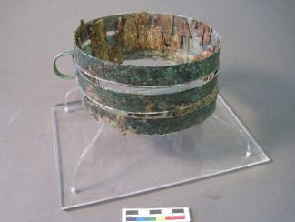
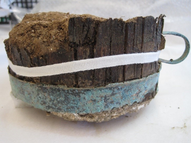
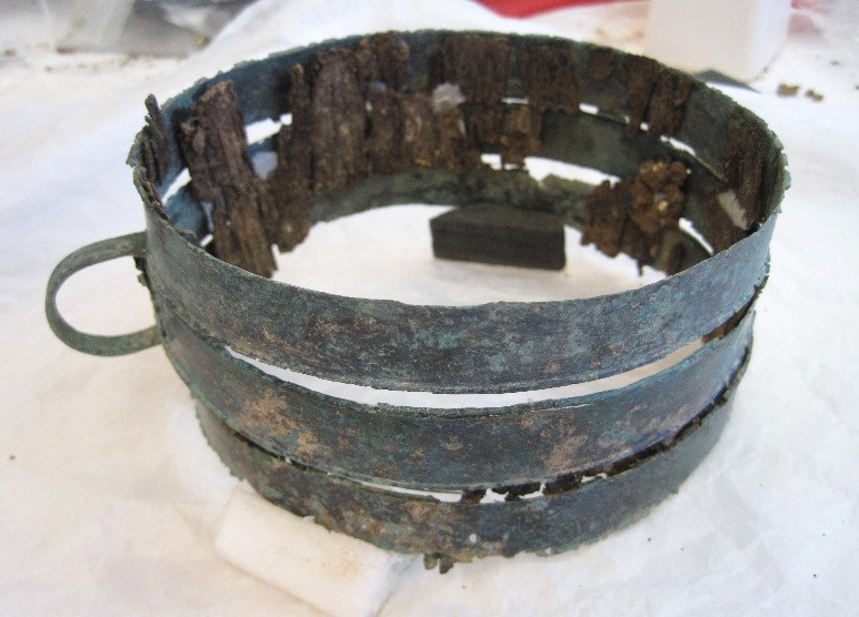
Following the lengthy process of acquiring the Oakley Hoard, permission was given for me, HCT’s Archaeology and general objects conservator, to begin work in August 2019. Freshly excavated material is fairly rare through our labs, which usually deal with museum objects, and so I wasted no time getting involved. I had already been able to take the step of x- raying the hoard; x-radiography being non-invasive and leaving no residual effect. It was therefore possible to produce plates in advance of acquisition, capturing information at an early stage for the object record and producing a preview of what might be expected during micro-excavation. The most fragile items, such as the copper alloy and wood tankard (fig. 1), could even be x-rayed through their boxes, and following additional record photography it was with the tankard that interventive work began.
 |
 |
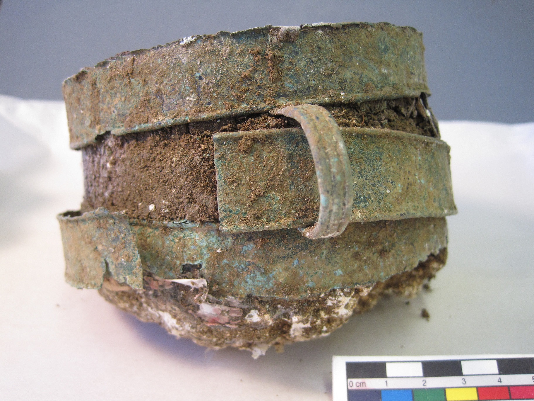
The tankard’s surface, particularly the upright laths of extremely fragile, degraded wood, was partly obscured by accretions of solid soil. Of three copper bands, one had split open at the seam and slipped down. The surface of the copper appeared mainly good, with minimal active corrosion and even some areas of un-patinated original colour. My first step was to mechanically remove as much soil as possible, to see what lay beneath. Small hand tools were used to remove all soil, concretions on the wood being softened with deionised water which was prevented from contacting the metal parts. The central band which had suffered from slippage was removed to prevent damage and to aid access; any wood remaining in situ secured with a small amount of reversible adhesive.
 |
 |
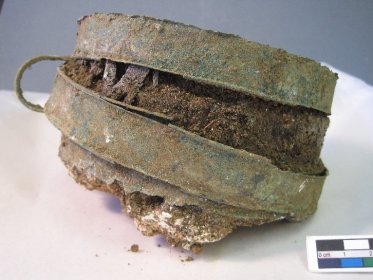
The removal of soil concretions freed the upper copper alloy band, which was also detached and put aside at this point (fig. 2). The wood was further cleaned with cotton swabs moistened in deionised water, in solution with Industrial Methylated Spirits, to prevent over-wetting and aid evaporation. It was now possible to see the number and condition of the remaining wood laths. These survived to a surprising extent, although their fragile structure required impregnation with a penetrating consolidant. Objects are often at their most fragile while wet, and the process of consolidation is no exception, so while the wood laths dried they were supported and encouraged to hold their shape with unbleached cotton tying tape (fig. 3). Structural consolidation is a lengthier process than surface consolidation or coating, as in order to ensure penetration of the consolidant, the solvent carrier used must be slow to evaporate – in this case mineral spirits fitted the bill.
Once the laths had dried, micro-excavation of the soil fill began, any emerging wooden splinters being cleaned and tacked back into place with reversible adhesive.
|
|
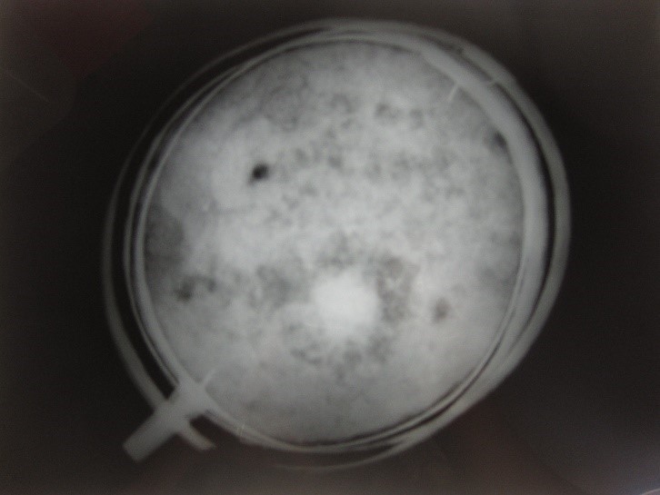
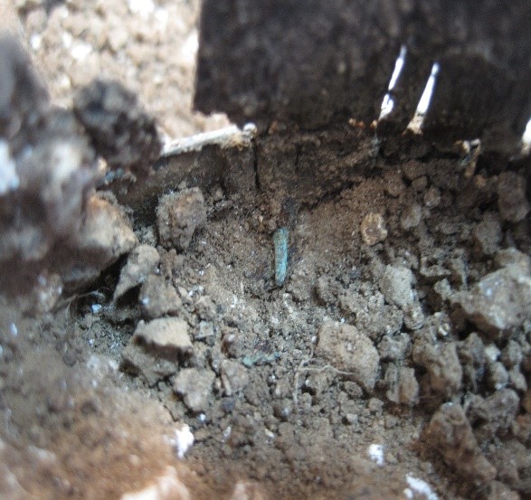
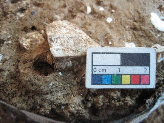
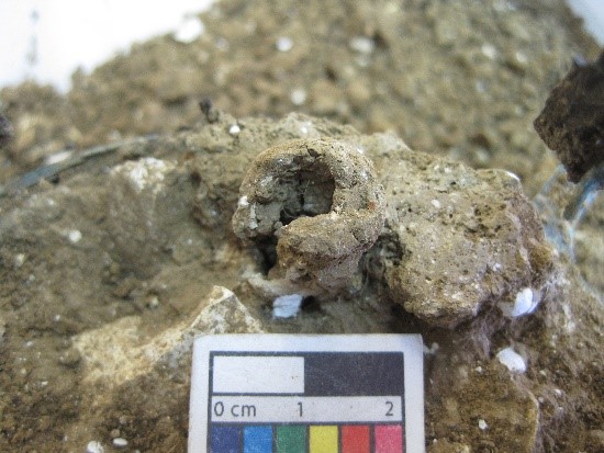
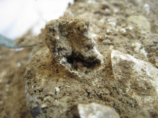
X-radiography (Fig. 4) had not revealed anything further than voids (possible root runs) and stones, although the presence of a rivet (fig. 5) on the opposite side to the handle had been noted. However, organic objects and ceramics are generally of a similar density to surrounding soil, and as such may not show up in x-rays. As such very gradual removal of the fill was necessary, recording anything of interest. Spits of around 15mm were removed, anything feeling or looking different being investigated. Hours spent whittling away at soil and flint can encourage an excess of optimism on encountering anything unusual, and I have not forgotten warnings in the field about creating a feature out of thin air. Yet I confess to having been very excited by what appeared to be a small ceramic bead (fig. 6). The ‘bead’ unfortunately quickly morphed into the upper part of a macaroni shaped, pale clay tube before widening out into what looked like a natural root run. Slight disappointment on my part (and perhaps the few people who I had happily told about my ‘bead’) – but in any case, the bead-like fragments were bagged and kept.
 |
 |
 |
A significant part of a conservator’s role is to retain as much evidence and information as possible, so as not to preclude any future interpretation or analysis. In this spirit, also retained were some truly tiny snail shells (time period unknown), a hard, rounded lump (substance unknown), some soft, spongy material which may (or may not) be either degraded bone or root, and – hurray for being able to identify something - one or two very small fragments of bone and charcoal.
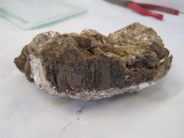
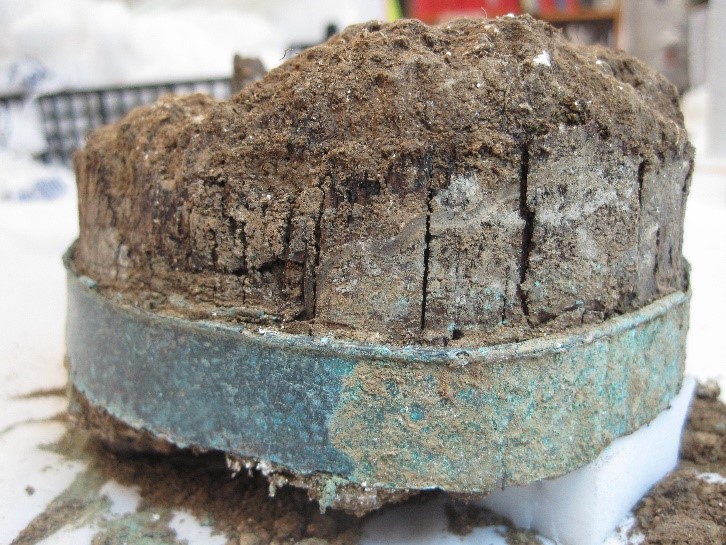
As the bottom layer approached, it became evident that the soil was now far chalkier, riddled with lumps of clay and root runs. There was also no evidence of any base to the vessel; the remaining fill finally releasing itself in a lump from beneath the tankard with some wooden laths attached. It was clear these laths could not be separated safely, so they were consolidated in situ upon a substrate of remaining chalk (fig. 7).
With the excavation complete and all parts cleaned and consolidated, only stabilisation and reconstruction remained. Chemical stabilisation of copper alloy is usually undertaken by bath in a vacuum chamber, to help the penetration of the neutralising chemical, benzotriazole (BTA), right down to the bottom of any active corrosion pits. However, there was no way the tankard would survive soaking, let alone a vacuum. Instead, applications of BTA solution were made by brush onto all accessible metal. Stabilisation would often be followed by a coating of Incralac (International Copper Research Association Lacquer), but in this case it was decided not to introduce anything which might hinder future applications of BTA.
Once dry, the detached copper bands were replaced in position (fig. 8). Joins were made and tears backed with a very thin Japanese tissue, adhered with reversible adhesive. When in-painted to match surrounding surfaces, these patches are virtually undetectable, but provide strength to weak areas, including any structurally weak wood. The adhesive used dissolves in acetone, rather than mineral spirits, so these patches can be removed if required without disturbing the consolidation of the laths.
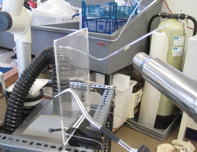
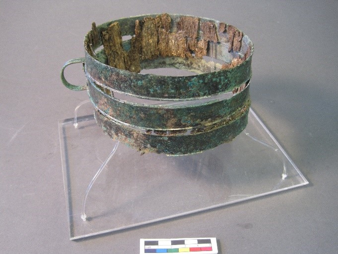
The final step was to provide support for the tankard. The best way to minimise risk from handling a fragile object is to create a mount that supports the object from box to display, removing the need for direct object handling. A little bit of recycling helped create a mount for the tankard, as a label holder rescued from an old museum display proved not only the perfect size for a base, but also came with pre-drilled holes in the corners, fitting my Perspex rod perfectly. All that followed was to cut and fit the rods, then carefully bend and shape them using a heatgun (fig. 9). The gentle springy tension of the rods was all that was needed to hold them in place inside the tankard (fig. 10), with final adjustments made to ensure no vulnerable areas were under tension.
Conservation of the Oakley hoard will continue over the next year and it is expected that the items will eventually be displayed in an appropriate HCT site – watch this space for future instalments!
|
|
From an article previously written for the Hampshire Field Club and Archaeological society newsletter No. 73, Spring 2020.